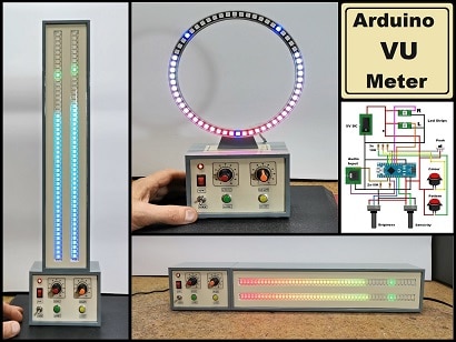
How to Make DIY Music Reactive RGB LED Ring (WS2812B) Using Visuino
2026-04-02 | By Ron Cutts
License: GNU Lesser General Public License LED Strips Microcontrollers Wifi Arduino ESP32
In this tutorial, we are going to make music reactive lights using an Arduino Nano ESP32 board with a Neopixel LED ring & microphone module using Visuino.
Every time the sound is detected, the LEDs will move and randomly change colors.
In case you do not have the microphone module, I will also add a step at the bottom to make the project without it.
Watch the video!
Learn more about Visuino: What is Visuino
What You Will Need
Arduino Nano ESP32 (or any other board)
Microphone module (Optional)
Breadboard
Jumper wires
Visuino program: Download Visuino


The Circuit
Connect the LED Ring pin [VCC] to the Arduino pin VBUS or 5V.
Connect the LED Ring pin [GND] to Arduino pin [GND]
Connect the LED Ring pin [IN] or (DI) to Arduino digital pin [6]
Connect the Microphone module pin [VCC] to Arduino pin [VBUS or 5V]
Connect the Microphone module pin [GND] to Arduino pin [GND]
Connect the Microphone module pin [DO] to Arduino digital pin [2]

Calibrate the Microphone
Slowly rotate the trimmer until the second LED is OFF and turns ON only if you make a sound.

Start Visuino, and Select the Arduino Nano ESP32 board type.
Start Visuino as shown in the first picture. Click on the "Tools" button on the Arduino component (Picture 1) in Visuino. When the dialog appears, select "Arduino Nano ESP32" as shown in Picture 2


In Visuino Add Components
Add "Clock Multi Source" component
Add "Random Color" component
Add "NeoPixels" component


In Visuino Set Components
Double-click on "NeoPixels1" and in the "PixelGroups" window, drag "Running Color" to the left
On the left side of the "PixelGroups" window, select "RunningColor1," and in the properties window, set "Count Pixels" to 12 or 16 (depending on how many LEDs your LED ring has)
Close the "PixelGroups" window


In Visuino Connect Components
Connect Arduino digital pin [2] to "ClockMultiSource1" pin [In]
Connect "ClockMultiSource1" pin [0] to "RandomColor1" component pin [Clock]
Connect "RandomColor1" pin [Out] to "NeoPixels> "RunningColor1" component pin [Color]
Connect "ClockMultiSource1" pin [1] to "NeoPixels> "RunningColor1" component pin [Step]
Connect "NeoPixels1" component pin [Out] to Arduino digital pin[6]


Generate, Compile, and Upload the Project
In Visuino, at the bottom, click on the "Build" tab, make sure the correct port is selected, then click on the "Compile/Build and Upload" button.

Play
After uploading the project to the Arduino Nano ESP32, the RGB LED ring will start to randomly change colors according to the detected sound by the microphone module.
Congratulations! You have completed your LED project with Visuino. Also attached is the Visuino project that I created for this. You can download and open it in Visuino: https://www.visuino.com
Project Without the Microphone
Add "Pulse Generator" component and connect pin [Out] to "ClockMultiSource1" pin [In]
Select "PulseGenerator1" and in the properties window, change the "Frequency" value to adjust the speed


Tips
Place the microphone module near the speaker of a radio, phone, or TV.